diff options
| -rw-r--r-- | docs/hand_wire.md | 104 |
1 files changed, 1 insertions, 103 deletions
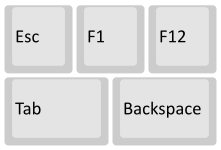
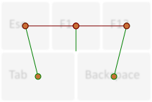
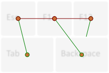
diff --git a/docs/hand_wire.md b/docs/hand_wire.md index 0a3773da19..d6de64f387 100644 --- a/docs/hand_wire.md +++ b/docs/hand_wire.md @@ -170,116 +170,14 @@ As you solder the wires to the controller make a note of which row/column is goi As you move along, be sure that the controller is staying in place - recutting and soldering the wires is a pain! - ## Getting Some Basic Firmware Set Up From here, you should have a working keyboard once you program a firmware. Simple firmware can be created easily using the [Keyboard Firmware Builder](https://kbfirmware.com/) website. Recreate your layout using [Keyboard Layout Editor](http://www.keyboard-layout-editor.com), import it and recreate the matrix (if not already done as part of [planning the matrix](#planning-the-matrix). -Go through the rest of the tabs, assigning keys until you get to the last one where you can compile and download your firmware. The .hex file can be flashed straight onto your keyboard, and the .zip of source files can be modified for advanced functionality and compiled locally using the method described in the collapsable section below, or using the more comprehensive [getting started guide.](newbs_getting_started) - - -### Creating and compiling your firmware locally (command line method) - -To start out, download [the firmware](https://github.com/qmk/qmk_firmware/) - We'll be doing a lot from the Terminal/command prompt, so get that open, along with a decent text editor like [Sublime Text](http://www.sublimetext.com/) (paid) or [Visual Studio Code](https://code.visualstudio.com) (free). - -The first thing we're going to do is create a new keyboard. In your terminal, run this command, which will ask you some questions and generate a basic keyboard project: - -``` -./util/new_keyboard.sh -``` - -You'll want to navigate to the `keyboards/<project_name>/` folder by typing, like the print-out from the script specifies: - -``` -cd keyboards/<project_name> -``` - -#### `config.h` - -The first thing you're going to want to modify is the `config.h` file. Find `MATRIX_ROWS` and `MATRIX_COLS` and change their definitions to match the dimensions of your keyboard's matrix. - -Farther down are `MATRIX_ROW_PINS` and `MATRIX_COL_PINS`. Change their definitions to match how you wired up your matrix (looking from the top of the keyboard, the rows run top-to-bottom and the columns run left-to-right). Likewise, change the definition of `UNUSED_PINS` to match the pins you did not use (this will save power). - -#### `<project_name>.h` - -The next file you'll want to look at is `<project_name>.h`. You're going to want to rewrite the `LAYOUT` definition - the format and syntax here is extremely important, so pay attention to how things are setup. The first half of the definition are considered the arguments - this is the format that you'll be following in your keymap later on, so you'll want to have as many k*xy* variables here as you do keys. The second half is the part that the firmware actually looks at, and will contain gaps depending on how you wired your matrix. - -We'll dive into how this will work with the following example. Say we have a keyboard like this: - - - -This can be described by saying the top row is 3 1u keys, and the bottom row is 2 1.5u keys. The difference between the two rows is important, because the bottom row has an unused column spot (3 v 2). Let's say that this is how we wired the columns: - - - -The middle column is unused on the bottom row in this example. Our `LAYOUT` definition would look like this: - -``` -#define LAYOUT( \ - k00, k01, k02, \ - k10, k11 \ -) { \ - { k00, k01, k02 }, \ - { k10, KC_NO, k11 } \ -} -``` - -Notice how the top half is spaced to resemble our physical layout - this helps us understand which keys are associated with which columns. The bottom half uses the keycode `KC_NO` where there is no keyswitch wired in. It's easiest to keep the bottom half aligned in a grid to help us make sense of how the firmware actually sees the wiring. - -Let's say that instead, we wired our keyboard like this (a fair thing to do): - - - -This would require our `LAYOUT` definition to look like this: - -``` -#define LAYOUT( \ - k00, k01, k02, \ - k10, k11 \ -) \ - { k00, k01, k02 }, \ - { k10, k11, KC_NO } \ -} -``` - -Notice how the `k11` and `KC_NO` switched places in the bottom portion to represent the wiring, and the unused final column on the bottom row. Sometimes it'll make more sense to put a keyswitch on a particular column, but in the end, it won't matter, as long as all of them are accounted for. You can use this process to write out the `LAYOUT` for your entire keyboard - be sure to remember that your keyboard is actually backwards when looking at the underside of it. - -#### `keymaps/<variant>/default.c` - -This is the actual keymap for your keyboard, and the main place you'll make changes as you perfect your layout. `default.c` is the file that gets pull by default when typing `make`, but you can make other files as well, and specify them by typing `make handwired/<keyboard>:<variant>`, which will pull `keymaps/<variant>/keymap.c`. - -The basis of a keymap is its layers - by default, layer 0 is active. You can activate other layers, the highest of which will be referenced first. Let's start with our base layer. - -Using our previous example, let's say we want to create the following layout: - - - -This can be accomplished by using the following `keymaps` definition: - -``` -const uint16_t PROGMEM keymaps[][MATRIX_ROWS][MATRIX_COLS] = { - [0] = LAYOUT( /* Base */ - KC_ESC, KC_F1, KC_F11, \ - KC_TAB, KC_BSPC \ - ), -}; -``` - -Note that the layout of the keycodes is similar to the physical layout of our keyboard - this make it much easier to see what's going on. A lot of the keycodes should be fairly obvious, but for a full list of them, check out [Keycodes](keycodes.md) - there are also a lot of aliases to condense your keymap file. - -It's also important to use the `LAYOUT` function we defined earlier - this is what allows the firmware to associate our intended readable keymap with the actual wiring. - -#### Compiling Your Firmware - -After you've written out your entire keymap, you're ready to get the firmware compiled and onto your Teensy. Before compiling, you'll need to get your [development environment set-up](getting_started_build_tools.md) - you can skip the dfu-programmer instructions, but you'll need to download and install the [Teensy Loader](https://www.pjrc.com/teensy/loader.html) to get the firmware on your Teensy. - -Once everything is installed, running `make` in the terminal should get you some output, and eventually a `<project_name>.hex` file in that folder. If you're having trouble with this step, see the end of the guide for the trouble-shooting section. - -Once you have your `<project_name>.hex` file, open up the Teensy loader application, and click the file icon. From here, navigate to your `QMK/keyboards/<project_name>/` folder, and select the `<project_name>.hex` file. Plug in your keyboard and press the button on the Teensy - you should see the LED on the device turn off once you do. The Teensy Loader app will change a little, and the buttons should be clickable - click the download button (down arrow), and then the reset button (right arrow), and your keyboard should be ready to go! +Go through the rest of the tabs, assigning keys until you get to the last one where you can compile and download your firmware. The .hex file can be flashed straight onto your keyboard, and the .zip of source files can be modified for advanced functionality and compiled locally using the method described in [Building Your First Firmware](newbs_building_firmware?id=build-your-firmware). ----- ## Flashing the Firmware |
